Sailing Vessel (SV) Sarah
Sarah has a new owner as of 7/26/2021. There will be no more updates to these SV Sarah pages
Sarah has a new owner as of 7/26/2021. There will be no more updates to these SV Sarah pages
| Simple Repairs | |
| I've created this page to document a few of the simple repairs I've done on Sarah and the onboard equipment. | |
| Gas Grill Mount, 2011 | |
| In 2010 I replaced the Force 10 propane grill on Sarah with one from Magma (the Cabo). Apparently Magma has taken over the boat and RV grill market in the US and Canada. Force 10 no longer makes a gas grill. Initially I was very happy with the Magma. The box-shaped cover gave more effective grill space than the Forec 10. The grill bars are in 3 sections, which can be easily removed for cleaning. The other components in the grill (grease deflector and burner tube) are also easily removed for cleaning or replacement. The whole thing is made of stainless steel so corrosion is not a major problem. | |
| After a year I did finally come up with something I didn't like about the grill - the rail mount. The rail mount is sold separately and attaches to a bracket on the underside of the grill. The bracket also holds the grease tray in place. The rail mount is actually a very sturdy piece of equipment. However the bracket it attaches to is fastened to the bottom of the grill with six (6) very small spot welds. | |
|
The Rail Mount Bracket for the Magma Cabo |
The first time I accidentally leaned against the (cold) grill while it was mounted on the rail those welds failed and the grill came loose from the bracket. I attempted to re-fasten the bracket using JB Weld, but either the grill generates a lot more heat than I thought or JB Welds lies about their product working in up to 600F. The first time I used the grill after re-attaching the bracket with JB Weld the bracket came loose once again. |
| The final solution was to through-bolt the bracket to the bottom of the grill. Fortunately Magma provided a nice lip on both sides of the bracket through which I drilled holes for the bolts. This is about 1/16" thick SS, so it took a little time to drill the four holes for the machine screws. |
Bracket Through Bolted to Bottom of Grill |
|
Nuts and Washers on Inside of Grill |
On
the inside of the grill the machine screws were secured with
small fenders washer and nuts. I probably ought to add
lock washers as well. My only concern about this fix is that the screw holes might leak a little grease. |
| Water Blockage in SeaFrost SA-3 Refrigeration, 2011 | |
| For several years I've
notice a gradual reduction in the water flow through the
SeaFrost SA-3 (Shore Assist) refrigeration. This unit has
a water cooled condenser and an automatic switch that will shut
down if the water flow is stopped. The water is fed by a
120VAC March Centrifugal Pump located under the cabin sole in
the main cabin. The condenser and compressor are installed
in a single cabinet which is located beneath the foot of
my berth in the aft cabin. There is a long (12') 3/8"
water hose that runs from the pump to the cabinet. Water
is fed to the pump from a manifold that also serves the A/C
and galley sea water faucet. The manifold is fed from a
1-1/2" through-hull and ball valve. So there is plenty of
feed water to satisfy all of the water circuits. The A/C
shows more than adequate water flow from the same size pump.
In 2010 I replaced the valve to the water pump on the manifold,
and I replaced the pump in 2011. Neither of those actions
helped the water flow. So clearly the problem is in the SA-3 water circuit. For the past two years I've berthed Sarah is some pretty skunky waters - Trent River, NC and Ortega Rive, FL. I suspected the water hose was getting clogged from the all the junk that was being pulled in from those rivers, in spite of the fact the manifold has a Groco water strainer to catch any debris that may be sucked in and a scoop strainer on the outside of the through-hull. I check and clear the strainer basket every 3-4 weeks, especially during the summer. |
|
| Finally on August 3, 2011, after two years of watching the water flow decrease, the flow stopped and the SA-3 shut down and would not restart for more than a minute before shutting down again. Now I would have to fix the clog. This was a major problem as my Engine-Drive compressor was also out of commision at that time. | |
In the picture on the right is the side of the SA-3 cabinet that contains the ports for water and refrigerant. The vinyl hose goes to the discharge through-hull. The water hose from the pump is on the far right side of the picture under the violet wiring. It is just barely visible even when you click on the picture and load it at full resolution. The only part of the that hose that is really visible is the hose clamp. I was not looking forward to trying to get that hose off and putting a new hose on. Fortunately my installer also had the same problem, so he put a 3' pigtail hose on the unit before mounting the cabinet in the locker. Then he connected the pigtail to the main hose with a Male-Male adpater. |
Ports on Side of SA-3 Case |
|
Running Dock Hose to the SA-3 |
The pigtail also gave me the idea to test the water flow through the condenser before starting on the hose replacement. I ran a dock hose from a spigot on the dock into the aft cabin (as shown on the left). |
| Then I connected the dock hose to the pigtail hose. |
Dock Hose Connected to SA-3 |
|
Good Water Flow From the Dock Hose |
When I turned on the dock spigot, some
really ugly black water came of the through hull. After a
few seconds it turned clear as shown on the left. So it does not look like there was a blockage in the condenser unless it was cleared by the dock water pressure. I turned on the compressor to see if the system would detect the good water flow. The compressor ran for several minutes with no problem. Then I realized this was a mistake. When the compressor came on it also turned on the water pump, but the valve from the manifold to the pump was closed. With no water flow to the pump I may have damaged it. The next step is to replace the main water hose, which will not be a pleasant task as it has a long run under the cabin sole. |
|
Up until today,
9/7/2011, I've had nothing but good things to say about the
installer of my SA-3 refrigeration. Today I was cursing
him. I'd finally gotten down on my hands and knees to pull
the old water hose out from under the cabin sole. It was then that I discovered that the installer had taped the hose and the electrical wire together every 6' before he fed them both under the sole. Now I just wanted to remove the hose, not the wiring, but some of those taped spots were nearly inaccessible from above the sole. Fortunately I added two more hatches in the cabin sole in 2010, and I was just able to get one hand on those tape spots and cut them blindly. If I had not put in those hatches I would have had to remove the wiring with the hose. Once I'd freed the original hose I hooked it up to that dock hose I used to test the condenser and turned on the water. On the right you can see the gunk oozing from the hose. No doubt where the blockage was. |
Gunk in Refrigeration Water Hose |
|
Normal Water Flow Through New Hose |
It was a lot easier to run the new hose
than to remove the old one. Within a couple of hours the
new hose was hooked up and the frig was turned on. The
picture on the left shows the water flow produced by the frig
water pump. Looks pretty much like the flow with the dock
hose, shown above. I got lucky and did not damage the water pump by running it dry during my test with the dock hose. I think the major issue with running the pump dry is that the motor will overheat and shut down. I learned this the hard way a few years later (see below). |
|
This repair allowed the SA-3 to work flawlessly for several more
years. However I continued to spend the next two winters
and several summers in the Ortega River in Jacksonville, Fl.
This river is the source of a lot of the gunk that came out of
the SA-3 water hose. In the sumer of 2014 the SA-3
repeatedly shut down again. I flushed the water line once
more, but the compressor still shut down beforec completing a
cycle. This time I was also running the A/C, which also
draws water from the manifold that serves the SA-3.
Monitoring the water flow out of the dischages for the A/C and
the frig I could see that the frig discharge essentially stopped
when the A/C kicked in. So the A/C was starving the water
flow to the SA-3. The manifold had been supporting the frig and the A/C for over 10 years without a problem, so I didn't believe there was anything wrong with the design of the manifold for these applications - especially since I moved the delivery from a 1" thru-hull to a 1-1/2" thru hull. So I guessed the problem was sludge accumulating in the manifold as it had in the hose to the SA-3. It took a couple of flushings of the manifold, but eventually I was able to restore solid water flow to both the A/C and the SA-3. I guess as long as I keep Sarah in skunky water like the Ortega and Trent Rivers I should expect to have to flush the hoses and the manifold every 2 or 3 years. |
|
|
Another year passed after the
manifold was flushed then the SA-3 started shutting down again.
This time the symptoms were a little different. The SA-3
appeared to be running fine with good water flow even with the
A/C running, but it would shut down short of completing the full
cycle and would not restart automatically. In this case flushing
the hoses and manifold had no effect on the problem. |
|
|
SeaFrost referred me to their local rep (Master Cool) in St.
Augustine, FL As soon as I described my problem, the tech
rep said the problem was the over temperature shut off in the
pump. I wasn't even aware that the pump had such a
feature. He said there is a small diameter pipe on the
pump which diverts a portion of the water flow into motor
housing to cool it. He also said it is not uncommon for
the silty water in our area to block or partially block that
tube and cause the pump to over heat and shut down. After
about 5 minutes the pump will have cooled off and be ready to
run once again. The repair is to remove the cover plate on the pump and run fishing line through the tubing to clean out the blockage. The intake port for the cooling water is shown in the picture on the right. |
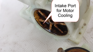 LC-2CP-MD Pump with Cover Plate Removed |
|
Before I could clean the pump it appeared to resume operation
with no shut down. I surmised that the blockage had been
cleared by water pressure enough to allow the SA-3 to complete a
cycle. However, I noticed the pump motor housing was very
hot to the touch. I knew the problem would return, but I
decided to buy a second pump for a backup before attempting the
clean the pump. I did not have a spare pump in this model,
and did not want to take the current one apart without a spare
handy. I hoped the existing pump would continue to
function long enough for the spare pump to arrive, which it did. When the new pump arrived I installed it and took the cover plate off the old pump as shown in the picture above. Notice that the interior of the pump has been badly discolored by the silty skunky water here in the Ortega River. |
|
| Engine-Drive Refrigeration Shut Down, 2011 | |
| Shortly after
Hurricane Irene
passed close to Sarah's berth off the Patuxent River I was back
on board Sarah getting ready to repair the rub rail damage from
the storm. Shore power had not been restored, so I used
the SeaFrost ED compressor to cool down the box. A few
days later shore power was restored and I switch back to the SA3
compressor. All seemed well until the SA3 shut down due to
the waster blockage problem described
above.
Then I switched back to using the ED compressor. After a few minutes of operation the clutch on the compressor released and the compressor stopped. I tried to restart the compressor, but each time it would shut down after a minute or less of operation. Now both of my refrigeration system were not operating. I checked the manual and the usual cause of this situation is low refrigerant pressue on the high pressure side of the system. Normally this would mean a refrigerant leak. Anything more than the most simple trouble-shooting of the refrigeration is beyond my knowledge and tool set. I attempted to get my original installer to work on the problem, but they are backed with the effects of Hurricane Irene and will not be able to work on it for several weeks. In the interim I cleared the blockage in the SA3 and restored my refrigeration with that compressor. |
|
|
SeaFrost Engine-Drive (ED) Compressor |
My suspicion was that the compressor (shown on the left) is leaking and will have to be replaced. In 2005, when returning to Florida from the Abacos I discovered that the sea water pump on the engine was leaking and showering the engine compartment with salt water. Much of this sea water landed on the compressor. I could not seal the pump leak so the compressor got a shower for another hour or so when we motored through the Ft. Pierce Inlet. I washed the compressor and the rest of the engine compartment with fresh water, and it lasted for another 6 years. I suspected that salt water bath finally caught up with the compressor. |
| On Sep 12, 2011 I moved Sarah to Zahnizer's Boatyard to fix the problem. The technician confirmed that the refrigerant level was very low. I started the engine and turned on the compressor while the technician re-charged the system. The compressor seemed to running normally. However the holding plates were already frozen from the SA3 compressor running. a better test was to let the plates thaw and then run the ED compressor. So I decided to stay overnight at Z's with the SA3 off and then run the compressor in the morning. No real answer on where the refrigerant leaked. The technician could not find any evidence of a leak in the system and surmised that it could just be a normal leakage in the 9 years since the system was installed. I was sceptical of that explanation, I'm also not anxious to spend $400 for a new compressor. | |
| The next morning I ran the
ED compressor to re-freeze the holding plates with no problem.
I was still skeptical that the re-charge was sufficient, so I
moved to an anchorage for 5 days and ran only the ED compressor
to maintain the freezer and frig. No problems found.
It looks like I have a slow leak in the system that currently
cannot be detected. As long as the ED continues to run for
another year or two without needing another re-charge, I'm
satisfied. Four years later (2015) the engine compressor is still running fine. |
|
| Temporary Latch For Anchor Well, 2011 | |
| The anchor well on the fore deck was secured by a handle that slides into a hole in the deck. At best this was not a very secure latch, but after 30 years the fiberglass around that hole had broken away and another means of securing the hatch was required. | |
| I really need to come up with a
completely different means of securing the anchor well hatch, if
I don't just glass over the foredeck entirely. Until I decide what I'm going to do with the anchor well, I need a means of keeping the hatch closed when underway in rough weather. My simple solution was to through bolt a small padeye to the deck over the hole into which the handle slides. I used a padeye with a diamond-shaped base so that the inner point of the diamond covered the maximum amount of the slide bar. The other three points of the base are through-bolted to the deck. This temporary solution has the advantage of providing a padeye on the fore deck into which I can clip my harness, when necessary. |
Hatch Handle Secured Under Padeye |
| Yanmar Engine Impeller Failure, 2012 | |
| I
repowered Sarah with a Yanmar
4JH4AE engine in January, 2008. Since that time I've
never had to replace the seawater impeller. The first time
it failed I was in Deaton's Boatyard in 2009 with a mechanic
onboard and he replaced the impeller. The failure was
caused by starting the engine with the seacock closed, which
destroyed the impeller, the failure was not caused by the
impeller. My experience with my previous boat and engine (Volvo MD6B) was that impellers failed within a few hours of installation or ran nearly forever. So I've never replaced an impeller as a preventive maintenance function. I just waited for one to fail, which is almost never. My recent experience may be cause to adjust that reasoning. In September, 2012 the impeller on the Yanmar engine failed and I was forced to do the replacement myself. The failure ocurred shortly after I had cleaned the basket in the Groco raw water strainer. I started the engine and an initial flow of water came out of the exhaust and then stopped. My immediate thought was that during the strainer cleaning I allowed something to clog the water hose. That same strainer serves both the Yanmar engine and the Northern Lights generator. I started the generator and saw normal full water flow out that exhaust. Clearly the problem was down stream of the strainer and most likely the impeller in the sea water pump on the engine. Why the impeller would fail at this time was a mystery, but it was the first place to look. I removed the cover plate on the water pump and I could see at least one vane on the impeller was gone. The first step was to remove the old impeller. This proved to be more difficult than I expected. It tried needle nose pliers, regular pliers, and channel locks with no success. The impeller just would not budge out of the pump housing. I resisted the common practice of using two screw drivers to pry the impeller out because of the danger of damaging the pump itself. Finally I resorted to spray some PBlaster onto the pump shaft and then used the two scewdriver technique to remove the impeller. |
|
| In the picture on the right you can see the failed impeller with two vanes missing. There was no debris in the pump, so those two wanes must be somewhere in the system. They likely provided the blockage for the sea water as the impeller will still move a lot of water with a couple of missing vanes. That missing debris was likely somewhere in the engine water hoses. I initially disconnected the hose between the pump and the oil cooler and blew out whatever was in that hose into the Zip-Loc bag on the right. There is part of one vane in that bag. Clearly there must be more debris somewhere. |
Old Impeller and Debris |
| Next I disconnected the hose
from the oil cooler to the heat exchanger and blew whatever was
in that hose and cooler into the Zip-Loc on the left. That
picked up a little more debris, but not enough to account
for two missing vanes. I checked the intake to the
heat exchanger and found nothing there. I was reluctant to install the new impeller and put everything back together without accounting for all of the impeller debris that might be in the system. I didn't want to burn up another impeller. I finally reasoned that any remaining debris must be in either the heat exchanger or oil cooler passages. If that debris was blocking the water flow, then a major cleaning of the heat exchanger or cooler would be required. Before going down that path I decided to put everything back together and start the engine to see if there really was still a water blockage. I felt there was a good possibility that the remaining debris may have come out of the pump during my many attempts to free the impeller. So I greased the inside of the pump housing, cleaned the pump cover plate, inserted the new impeller and finally reconnected all of the water hoses. I started the engine and within a few seconds I could see full water flow coming out of the exhaust. I put the engine in gear, raised the RPMs to around 1200, and let the engine come up to temperature. I shut down the engine after 20 minutes with no over-heating. My lesson-learned here is that maybe it is not a good idea to wait for an impeller to fail before replacing it. In the future I will replace, or at least check, the impeller every 2 years as part of a maintenance plan. |
|
| How Not To Fix a Burner on a Force 10 Stove, 2012 | |
| I had hoped that within a few days
I would be able to change the title of this section to "Fixing a
Burner on a Force 10 Stove," but the title above
still accurately describes the situation. Over the last year the stove top burners on my Force 10 have been getting more and more difficult keep lit, both on initial lighting and when reducing the flame for a simmer. This is normally a problem with the thermocouple on the burner, which shuts off the gas to the burner if the temperature drops below a certain level. This prevents the stove from venting gas into the cabin if a burner goes out due to a breeze or a spill. When the burner won't light or stay lit it usually means the thermocouple needs to be cleaned of grease buildup or the electrical ground on the thermocouple needs to re-seated. This action first requires removing the burner top and the flame spreader base. |
|
| The burner top and base are held
to the stove top by two small bronze machine screws. I
discovered the screws on this burner (and the other two as well)
were frozen and I could not remove them with a small Philips
screw driver. I tried to use force one of the screws and
only managed to break off the head of the screw. The other
I decided to drill out. Now I could remove the burner top as shown on the right, but I could not remove the base to be able to service the thermocouple (the conical-shaped item at the front of the burner. |
Burner Top Removed After Breaking/Drilling the Screws |
|
The Remnants of One Machine Screw Sticking out of the Burner Base |
There is a small bit of each screw
sticking out of the base. I tried to put a small
Vice-Grips on one screw remnant to see if I remove it, but only
managed to break off a little more of the screw. Fixing this problem is probably going to require dismantling the back of the stove to gain access to the underside of the stove top. Before starting down that path I asked for advise from Force 10. Their response was to replace the entire burner. I was able to squirt some degreaser onto the thermocouple and the burner is working again, but with a loose top. I have continued to use the burner for several months with no problems. I don't think I'll replace the burner just to fix 2 broken screws. |
| In 2014 I replaced the stove with a new Force 10 Euro model. Force 10 has completely re-designed the burners on this stove and the burner caps are no longer secured with small machine screws. | |
| Rudder Post Bushing, 2010 | |
| In 2010 I received an email from Jack & Patricia Tyler as they were crossing the Pacific on Whoosh, another 424. Jack detected some vibration while sailing. He climbed down into port cockpit locker and noted that there was a bushing on the rudder post that should support the post where it passed through a cross beam. The bushing had ridden up above the beam and the rudder post could move inside the hole in the beam. He pushed the bushing back down into the hole and put a hose clamp above it on the rudder post to keep it move riding up again. | |
| The next day I climbed down into my locker and discovered the same situation on Sarah shown in the picture on the right. I pushed it back in place, but didn't implement Jack's solution. A few years later (2015), I still have done nothing about the problem. Time to at least push the bushing back in place once more. |
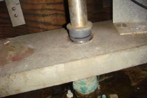 Bushing on Rudder Post Rides Above the Cross Beam |
| Galley Sink Drain, 2016 | |
| I've had to remove the double galley sink on several occasions, and each time I got a good look at the hoses and fittings for the drains. This is the original arrangement installed by Pearson in 1978, and I knew I would have to replace it one day. Each time I was put off by having to find replacements for the components that appeared to be neither standard household or marine items. |
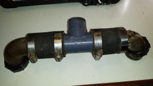 Galley Sink Drain Fitting |
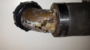 Corroded Brass Elbow |
The non-standard components are primarily the two brass elbows that are used to connect the sink drains to the "T" fitting which combines the drains into a single hose that runs to a ball valve below the waterline. Eventually one of those elbows corroded through (see picture on the left) and more water was draining onto the cabin sole that out the seacock. My long period of procrastination was over. |
| The first task was to find replacements for most if not all of the components. Fortunately the drains in the sink are standard houshold items (actually a bar sink). I was able to find standard plastic elbows at a local hardware store and also purchased new flexible couplers to put the components back together. I did need to cut down the length of the drain fitting tubes, but other than that it was essentially a direct replacement. |
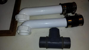 Household Drain Fittings and Original "T" Fitting |
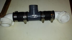 New Drain Elbows and Flexible Couplers Attached to the old "T" |
Of course it was not really a straight forward repair. It did involve 3 trips to the hardware store (a very good record for me). The 2nd trip was because I did not understand how the couplers are sized. They are labeled for I.D. of the pipes that are being coupled, but they are also sized to the type of pipe or tubing. The coupler must fit over the outside of the pipe and galvanized metal has a larger O.D. than PVC. Naturally I got the coupler for the wrong material and had to make an exchange trip to the store. |
|
The third trip was due to my cutting one of the elbows about
1/2" too short. You can see in the picture on the right
that the elbow on the outboard sink (rightmost) is longer than
the one on the inboard sink (leftmost). I missed that when
cutting the tubing. Well 3 trips to the store is pretty good for my repairs, so this was one of my better efforts. Now I have to wash 2 days worth of dishes. |
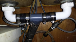 Repaired Drain Fittings in Place |